3 Position Ignition Switch Wiring Diagram Wiring Diagram
The battery wire will find a connection with the fusebox. In some cases, the accessory wire will do the same. 5 Pole Ignition Switch Wiring Diagram: Step 3 Strip down ¼ of the insulation of each of the five wires, then match a terminal connector to their ends with pliers.

3 Position Ignition Switch Wiring Diagram Wiring Diagram and Structure
How to Wire an Ignition Switch? The wiring for an ignition switch is very different depending on the type of vehicle you have. Modern car models can also have many different wires going to the switch, such as the immobilizer etc. But here's how older ignition switches are wired and how you can wire your own ignition switch into a vehicle.
6 Terminal Ignition Switch Wiring Diagram Briggs And Stratton 6
mankk 3 Wires Ignition Switch with Key 12V Universal Engine Starter Key Switch Off/On/ (Start) 3 Position with 2 Keys for Car Motorcycle Tractor UTV ATV Modified Car M-043. Amazon. $ 9.99. MGI SpeedWare 3-Wire Universal Ignition Key Switch for Cars, Buggies, Mowers and Go Karts, Off/On/ (Start) Amazon. $ 9.95.

3 Position Ignition Switch Wiring Diagram Emgo Universal Ignition
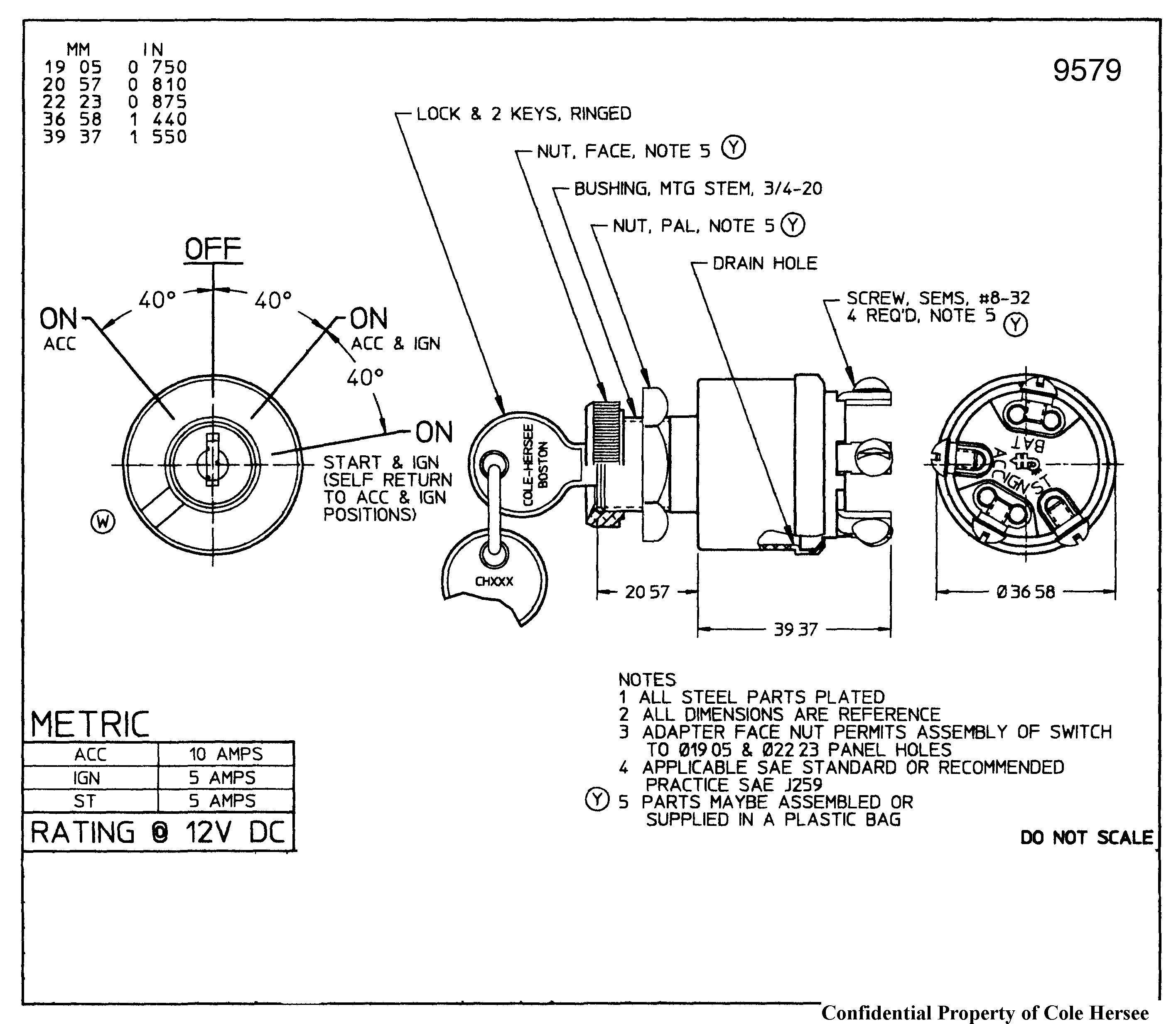
A 3 position ignition switch is a type of switch that is used to control the ignition of an engine. It is typically located on the dashboard of a vehicle and has three positions: Off , Run , and Start . The Off position disconnects the battery from the ignition system, preventing the engine from starting. The Run
3 Position Ignition Switch Wiring Diagram Database
11. Connect the Starter Wire: Join the starter relay wire to the "ST" terminal of the ignition switch. The "ST" terminal only activates when the ignition switch is turned to the "START" position or Position III. 12. Connect the Ignition Wire: Join the ignition wire to the "IGN" terminal of the car's ignition switch.

3 Position Ignition Switch Wiring Diagram Current News
If necessary, consult an ignition switch wiring diagram for your vehicle to be sure of the terminals' labels.. Place the car key in the ignition and turn it to the ACC (accessory) position. This is necessary to press the release pin so you can remove the ignition switch from the module..

Typical Ignition Switch Wiring Diagram
The 3 position ignition switch is made up of three wires: a positive wire, a negative wire, and a control wire. The positive wire is the one that sends power to the ignition switch, while the negative wire is the one that sends power away from the ignition switch.
3 Position Ignition Switch Wiring Diagram Wiring Diagram
Step 1: Park the Vehicle Ensure that your vehicle is parked on level ground before turning off the engine. Step 2: Ascertain the Terminals on the Ignition Switch Ascertain and locate the pins on the back of the vehicle's ignition switch.
3 Position Ignition Switch Wiring Diagram / Pollak Ignition Switch
To ignition system To starter motor solenoid To accessories e.g. radio, lights, cigar sockets etc. IGNITION SWITCH Brass terminals on switch Wiring Diagram For 4 Position Universal Ignition Switch Product Code P00940

3 Position Ignition Switch Wiring Diagram / Pollak Ignition Switch
Position 1: Off The first position of the ignition switch diagram is the "Off" position. This is the default state of the switch when the engine is not running. In this position, the ignition switch is disengaged, and the electrical circuit that powers the engine and accessories is disconnected.

3 Position Ignition Switch Wiring Diagram Free Wiring Diagram
Start Position: When the ignition switch is turned to the start position, it activates the starter motor, which cranks the engine to start it. This position is used when you want to start the vehicle's engine. Now let's discuss the wiring connections of a 3 position ignition switch.

Three Position Switch Schematic
At its most basic level, a 3 position ignition switch wiring diagram consists of a battery, starter, ignition switch, and a few other components, such as relays or fuses. The specific purpose of the diagram is to show the path that electricity takes as it moves through the components needed to start the engine.

3 Position Ignition Switch Wiring Diagram Free Wiring Diagram
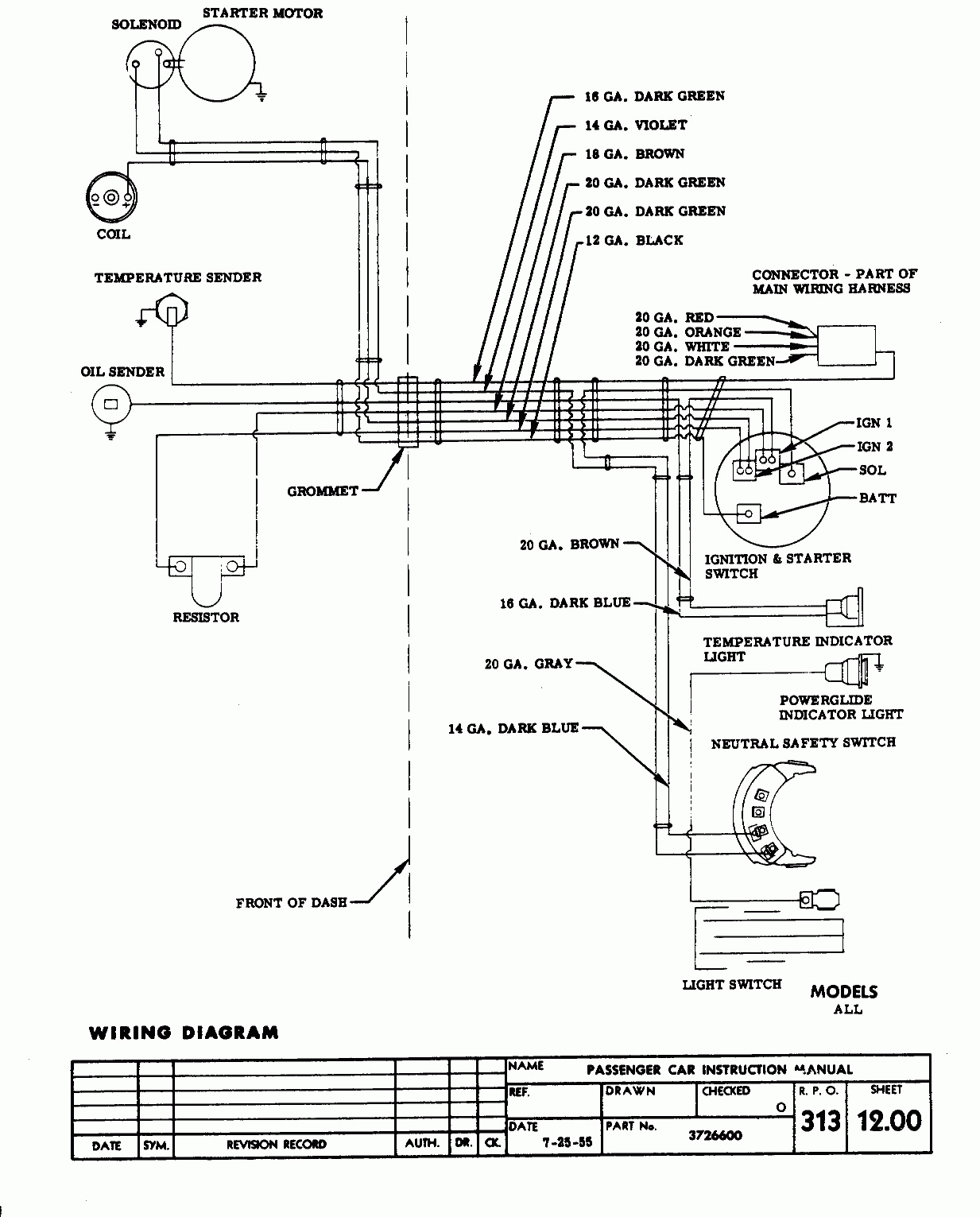
The ignition switch wire diagram provides a visual representation of the wiring connections between the ignition switch and other components. It shows the specific colors of the wires and how they are connected. This diagram is essential for identifying the correct wire for a particular function and ensuring proper installation and connection.
Key Switch Wiring
This wiring diagram shows how to connect your MASTERCELL inputs to a typical ignition switch. Image of wiring diagram showing how to wire an ignition switch with the Infinitybox system. As mentioned above, the MASTERCELL inputs work by getting connected to ground. To do this, you are going essentially wire the switch backwards.
3 way ignition switch wiring
A Guide to Understanding 3 Position Ignition Switch Wiring Diagrams The wiring of a three-position ignition switch can seem complicated, but with a bit of knowledge and patience, it can be done safely and correctly. The most common type of three-position ignition switch is used in cars and motorcycles, and it controls the ignition switch.

Ignition Switch Circuit Diagram Wiring Draw
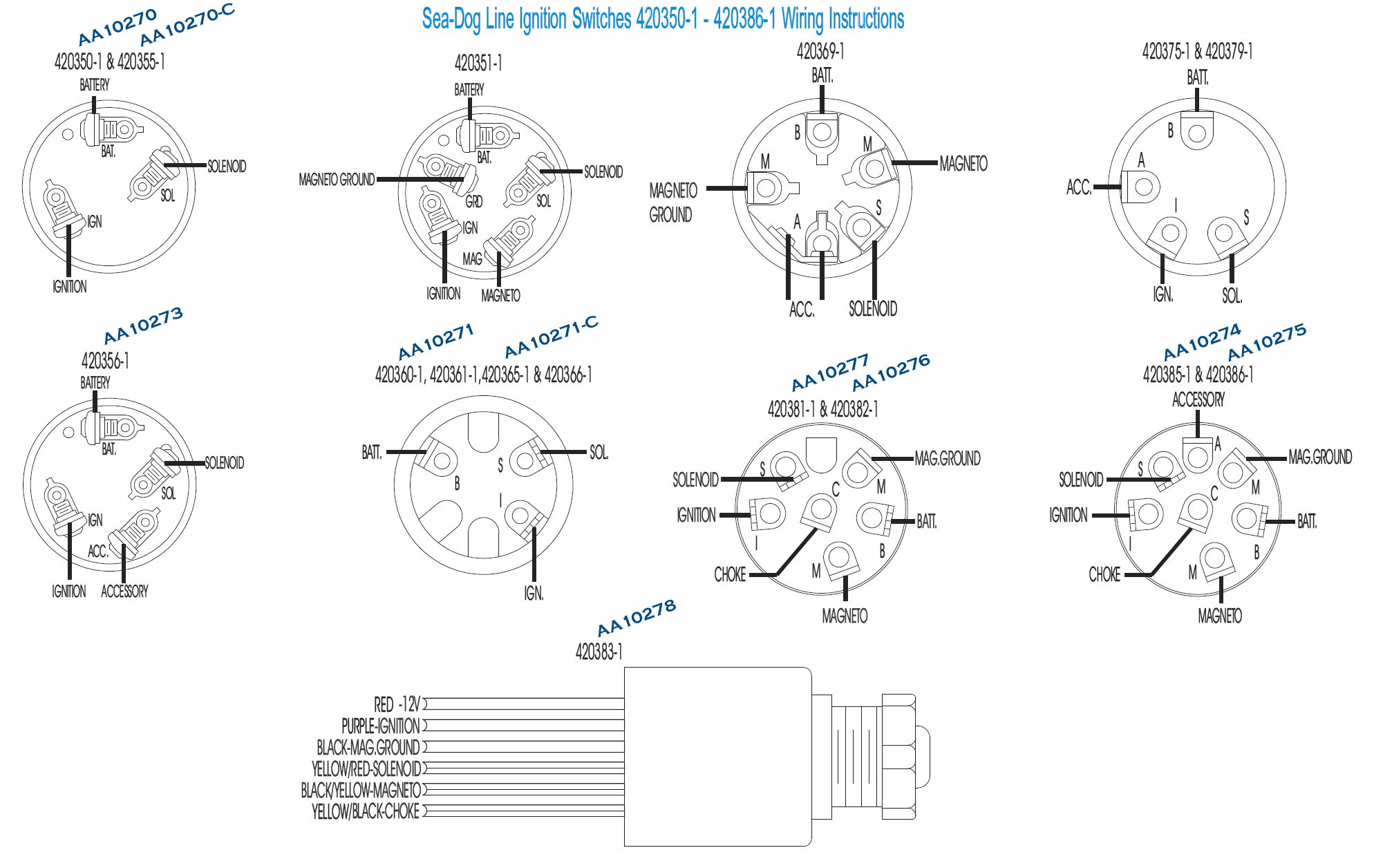
An ignition switch wiring diagram will provide the boater with an easy-to-understand overview of the process for replacing or repairing the ignition switch and associated components. The wiring diagram will break down the different components that make up the ignition switch and provide detailed instructions on how the connections should be made.