Fan Regulator Circuit AC Dimmer Ceiling Fan Regulator
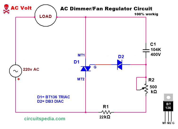
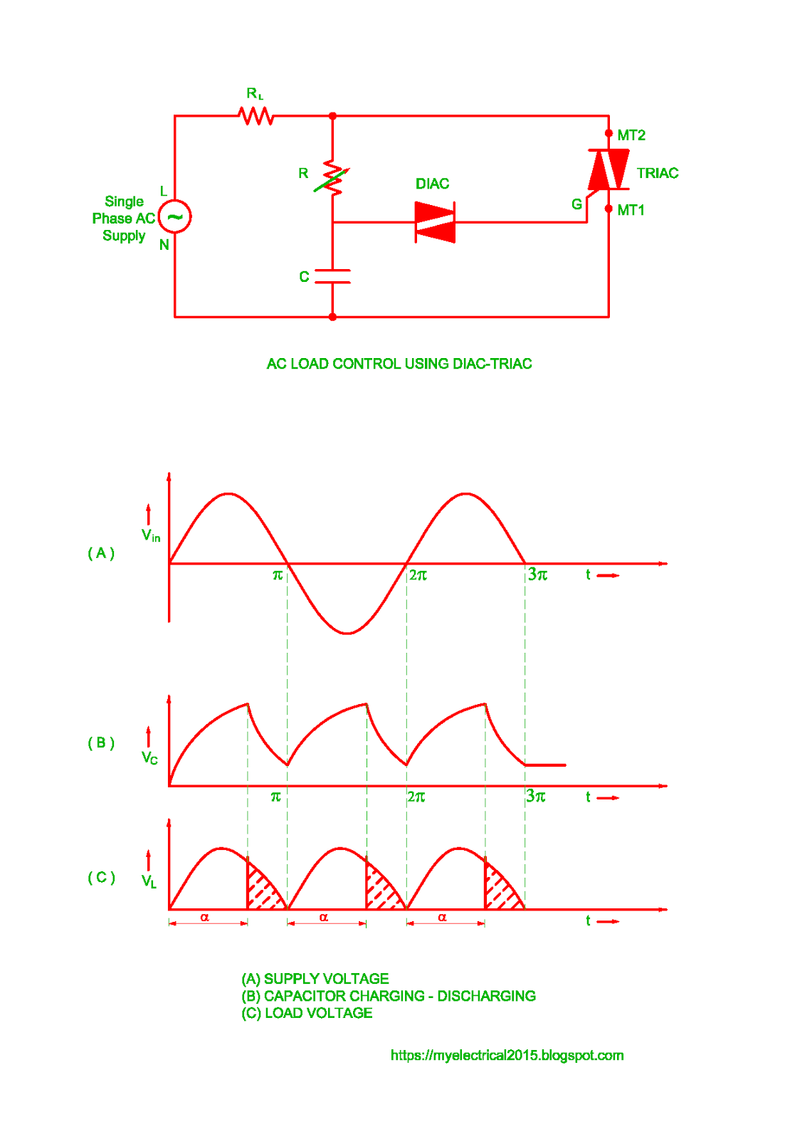
A simple electronic ceiling fan regulator circuit using a triac and a diac is a common type of circuit which is used to control the speed of a ceiling fan. This circuit basically works using phase control principle, in which the voltage supplied to the fan motor is varied by controlling the firing angle of the triac.

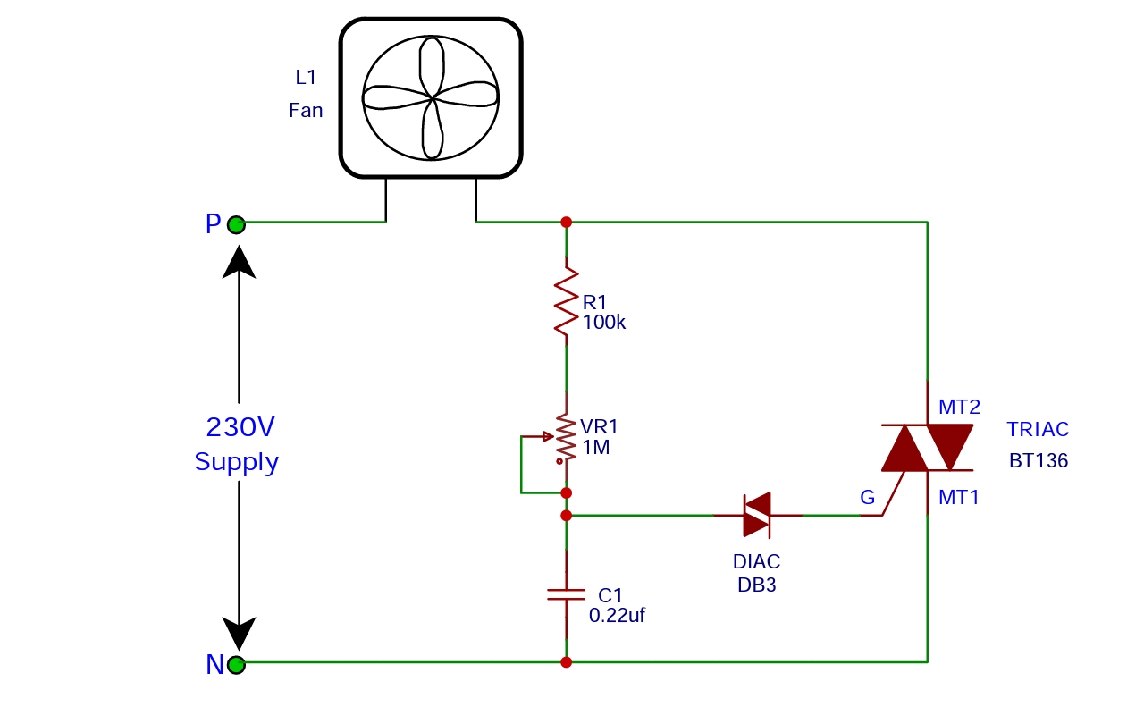
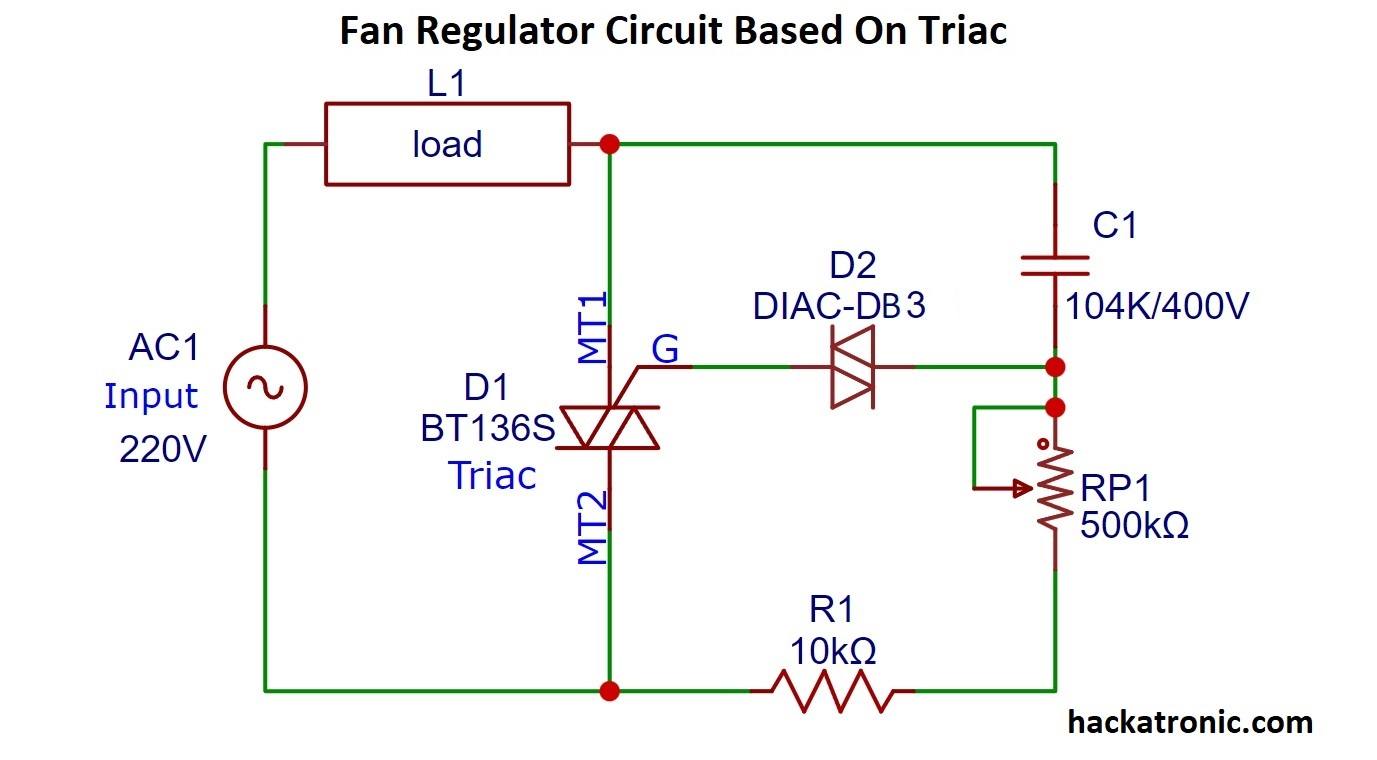
fan regulator circuit diagram
Thank you for watchingHow fan Regulator worksFan Regulator working principleFan regulator circuitBt136projectCheck out my other videos by clicking #freecircu.

Pin on
In this Ceiling Fan regulator circuit, the power supply phase line is connected to one terminal of the fan, and the other terminal of the fan is connected to the regulator circuit, which includes a TRIAC connected across the fan and a neutral power line, a DIAC connected to the gate terminal, and a polymer capacitor connected to a potentiometer.
Simple Fan regulator circuit Diagram Soldering Mind
Circuit Operation Referring to the shown remote controlled fan dimmer circuit, three main stages may be seen incorporated: the infrared signal sensor stage using the IC TSOP1738, the Johnson's decade counter, sequencer using the IC 4017 and a PWM processor stage using the IC 555.
Remote Controlled Fan Regulator under Repositorycircuits 26837 Next.gr
When fan control is augmented by fan-speed monitoring, a speed-control loop can be implemented that is independent of manufacturing variances and wear on the fan. In addition, a fan that is about to fail can be identified so that it can be replaced before it fails.
Triac Basic Operation Electronic Circuit Diagram Gambaran
The AC fan regulator circuit diagram is given below. The 220V AC mains voltage is given as the input to the one terminal of the fan (load) and the other terminal of the fan is connected to the one leg of the 10K ohm resistor.

Dhawan Electronics Fan Regulator Circuit at Rs 30/piece in Faridabad ID 9846909188
A ceiling fan regulator circuit is designed to control the speed of a ceiling fan, allowing users to adjust the airflow according to their comfort level. It ensures energy efficiency by reducing power consumption when lower fan speeds are selected. The circuit also provides a gradual change in fan speed to prevent sudden jerks or noise generation.
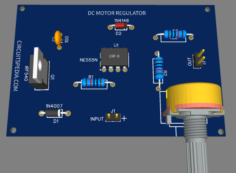
12v DC FAN Motor Speed Controller Regulator Circuit Diagram
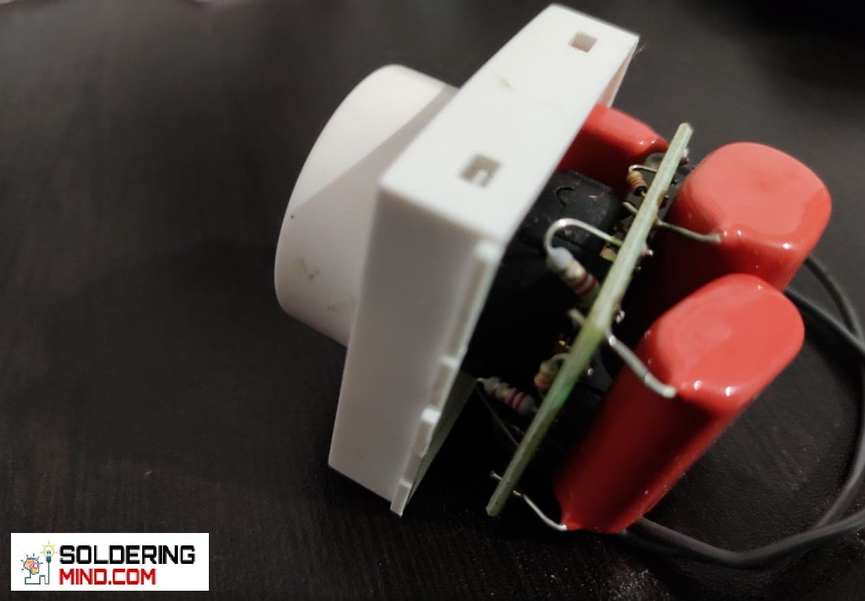
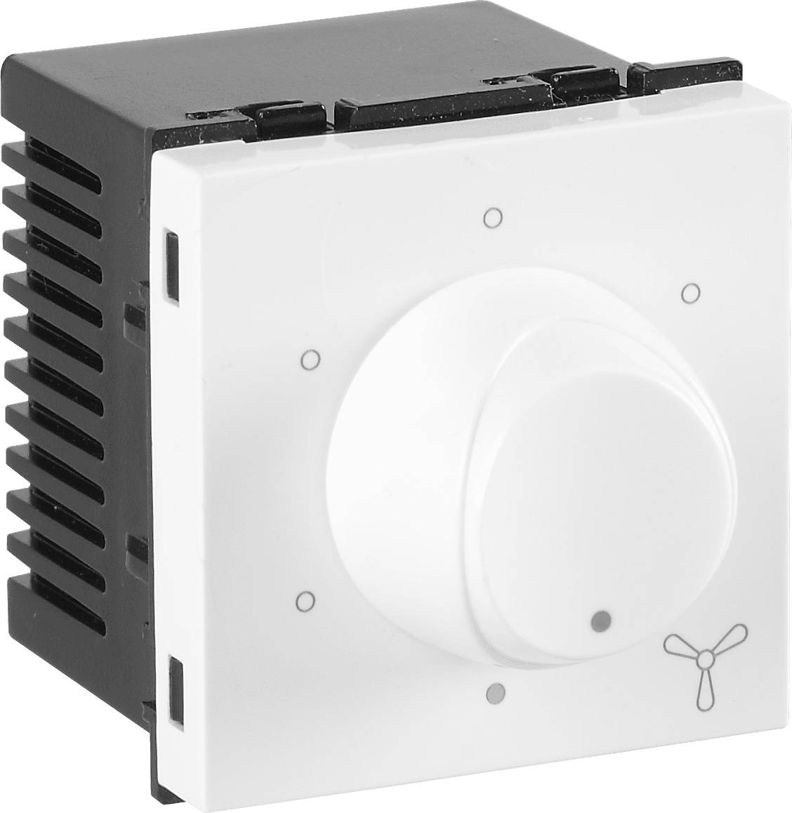
TRIAC is used in the domestic fan speed control circuits. In the TRIAC-based electronic fan regulator circuit, the main components used are a resistor, capacitor, DIAC, and TRIAC.. Structure of Fan Regulator The plastic knob which is connected to potentiometer (a variable resistance) is shown in the image above. When we rotate the knob, the.
5 Step Fan Regulator High Speed
Ceiling Fan regulator circuit. By using Triac, Diac and variable resister elements we can create effort less ceiling fan regulator and this regulator circuit regulates ceiling fan speed smoothly. Ceiling Fan regulator connection diagram. Construction and Working. The power supply phase line is connected with one terminal of fan and other.

Fan Regulator Connection Diagram and Internal Circuit Explanation ETechnoG
AC fan regulator circuit The main advantage of this type of regulator is cheap, highly durable and no humming noise is produced in a fan at low speed. Disadvantage - Even at low speed they consume the same power as high speed because resistive wire acts as a load in series with fan. Power loss is unnecessary by heat. Electronic Fan regulator
Automatic Fan Speed Regulator
1. They provide a continuous speed control. 2. Power saving at all the speeds. 3. Smaller size and weight. The heart of the electronic fan regulator is TRIAC. TRIAC is a semiconductor device belonging to the family of thyristors. Fig. 1: Front and back Images of Electronic fan Regulator

Fan Regulator Circuit, 50100 W, Rs 40 /piece India ID 4705838233
The fan regulator is triggered when torch light fall on LDR 1. In every focus of torch light the resistance of LDR 1 goes low which trigger IC 1. The every monostable clock is counted by decode counter IC 2, given to pin 14 or clock pin as shown in circuit diagram. The output of IC 2 is given to IC 3 and IC 4 parallel.
electronic fan regulator circuit diagram Wiring Diagram and Schematics
A fan regulator is a crucial component that serves to increase or decrease the speed of your fan according to your needs. You have a choice between conventional and electronic regulators. The technology along with the circuitry that controls the fan speed is quite complex. Conventional Regulators
electronic fan regulator circuit diagram Wiring Diagram and Schematics
A) Triac Based Fan Regulator : In this triac based fan regulator circuit, you need four main components i.e. capacitor, resistor, Diac, and Triac itself. A triac is a semiconductor device it belongs to the family of thyristors, it is a PNPN type device. A triac manly works as an AC switch and a solid-state relay.
Light Dimmer Circuit OR Fan Regulator Circuit OR AC Load Control Using TRIAC DIAC Electrical
T his is the circuit diagram of the simplest lamp dimmer or fan regulator. The circuit is based on the principle of power control using a Triac. The circuit works by varying the firing angle of the Triac. Resistors R1, R2 and capacitor C2 are associated with this. The firing angle can be varied by varying the value of any of these components.

PCB Design PracticalFan Regulator Androiderode
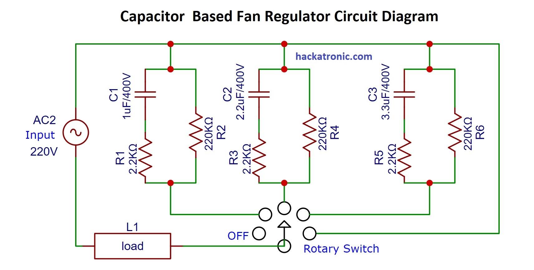
This simple fan regulator circuit is implemented using very simple components. Have you ever come across using a conventional fan voltage regulator to control the speed? Such type of regulator is called as Resistance Regulator, which works on the principle of a rheostat or a resistance potential divider arrangement.
